Sorry, no results were found, please try our filters or search again.
Have a video in mind for us to create?
Let us know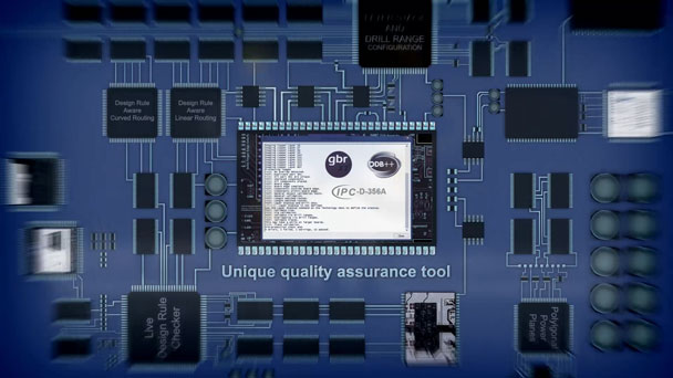

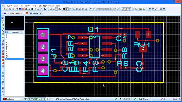
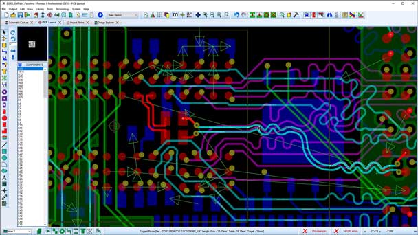
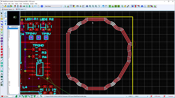
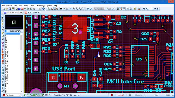
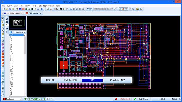
Proteus PCB Introduction
An introduction and overview of the Proteus PCB design software features. PCB CAD design made easier with with a powerful, easy to learn and use EDA solution.
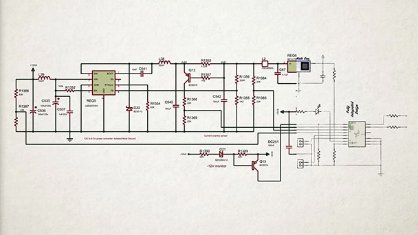
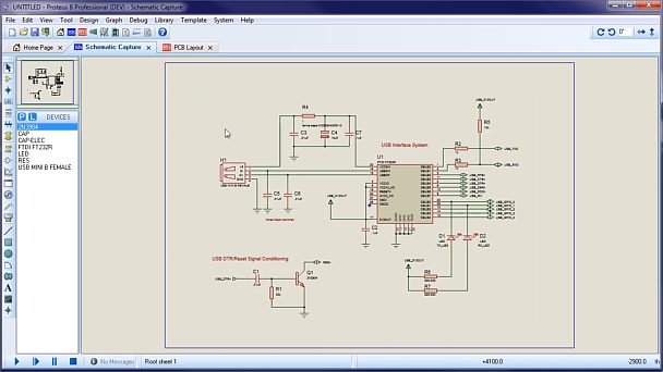
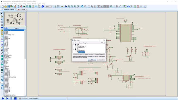
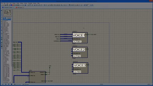
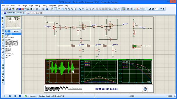
Proteus Schematic Capture
An overview of features included with the Proteus Schematic Capture software. Available with both PCB Design and Microcontroller simulation software options.

VSM Top Features
An introduction to a few of the top features and benefits of the Proteus VSM System with its unique tools for system simulation and development.
Proteus VSM
An introduction to a few of the many uses for the Proteus Embedded Simulation system. Real world applications - Get It Right First Time.
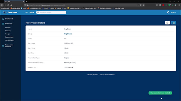
Licence Management Portal
How to use the Proteus Web Portal to mange a cloud licence for user groups and reservations, allowing access to the pool licence for those that need it when they need it.
IoT Builder by Proteus
A 60 second summary of how to create your IoT project using Proteus Visual Designer with IoT Builder for Raspberry Pi or Arduino AVR Simulation
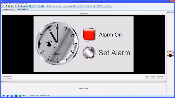
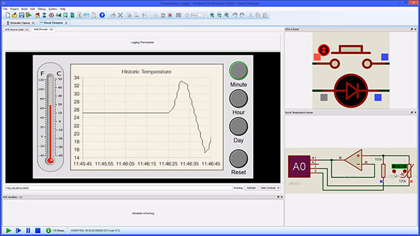
Introduction to Visual Designer
Proteus Visual Designer for Arduino simulation quickly and easily allows you to design and test Arduino projects without the need for programming experience.
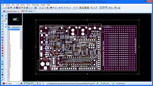
Tutorial: Getting Started
This video shows how to create a simple PCB in Proteus EDA Software from schematic capture through to completion of PCB Layout.
Tutorial: Proteus VSM
This video shows how to create a new simulation project from schematic capture software to final code completion using the Proteus embedded simulator.
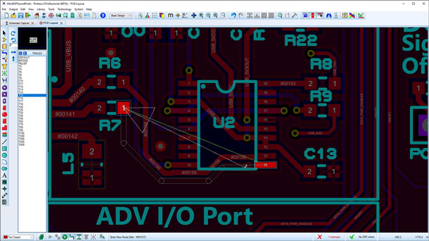
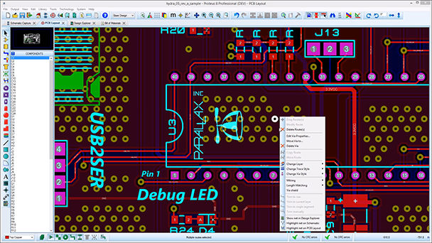
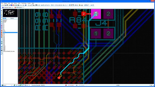
Tutorial: Manual Routing
This video gives an overview of the tools and features available when performing manual PCB routing operations in the Proteus Design Suite MCAD software.
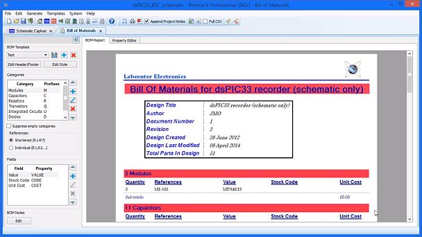
Tutorial: Bill of Materials
This video shows the functionality of the Bill of Materials module inside Proteus PCB Design software, linking both schematic capture and PCB layout.
Tutorial: Project Clips
This video shows how Proteus ECAD Software enables you to save snippets of your Schematic design and associated PCB layout for quick and easy reuse of common circuitry.
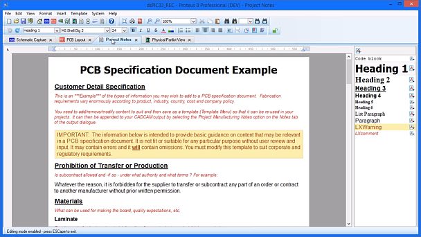
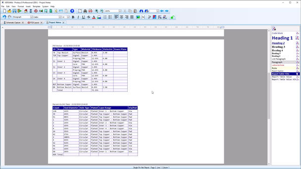
Tutorial: Project Notes
This video provides a short tutorial on how to use the Project Notes module within Proteus Design Suite allowing users to keep full documentation in the EDA software project.
Proteus 9 Overview
Presenting Proteus Design Suite version 9. Built from the ground up with a new, modern 64-bit framework and packed with new features Proteus 9 represents a huge leap forward in both performance and productivity.
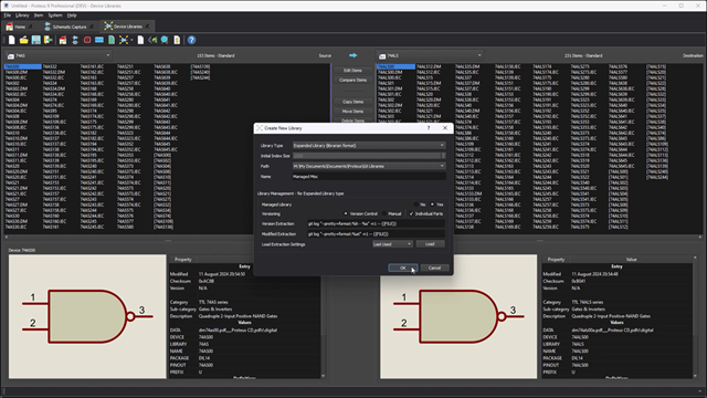
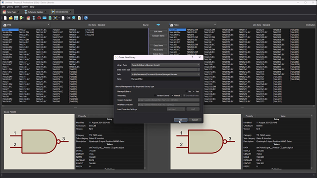
Proteus 9 Managed Libraries
Proteus 9 allows fully managed libraries to be used company wide. This is achieved through either manual or repository versioning, complete with validation checks both during the design process as well as file output generation.
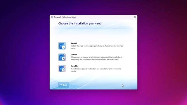
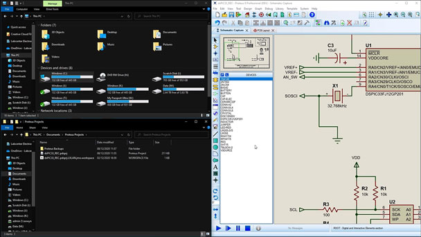
Proteus 9 Installation Methods
This video covers the installation methods for Proteus 9. It includes the standard typical installation to the newly added portable install and all associated file loactions.
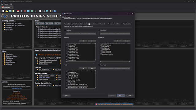
Proteus 9 Migration Tool
A quick video to show how to use the migration tool for a new installation of Proteus 9. This will migrate all your existing libraries, properties and templates across so you suffer no downtime on project work.
Proteus 9 Framework
This movie provides a brief guided tour of changes to the Proteus 9 application framework. This includes DPI aware sizing, colour themes, dockable windows, new system scope and much more.
Managed Libraries : Librarian (repo)
Proteus 9 includes support for managed libraries linked to a version control repository. This video shows how to set these up and distribute them among all required users.
Managed Libraries : Librarian (manual)
Proteus 9 includes support for managed libraries with manual library versioning. This video shows how to set these up and distribute them among all required users.
Managed Libraries : User Workflow
This video shows how to set up for using authorised managed libraries only for project creation. These come from either format of versioned libraries, either manual or repo.
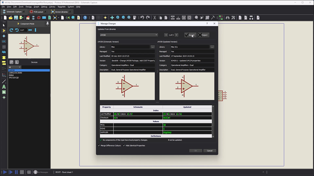
Managed Libraries : Reviewer
This short video shows how someone can review a design and parts used against those of the approved, versioned libraries, and update devices as required.
System Scope
Proteus now includes a live system scope for probing your design during simulation. As simple as placing a probe when simulation is running and you get live readings in the same view.
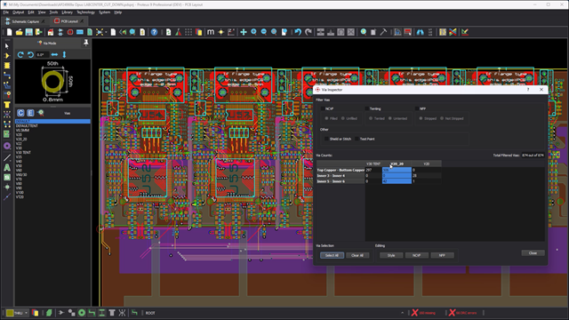
Via Inspector
The via inspector is a dialogue form in Proteus, allowing you to view and analyse via usage on the board, as well as make bulk edits to placed vias.
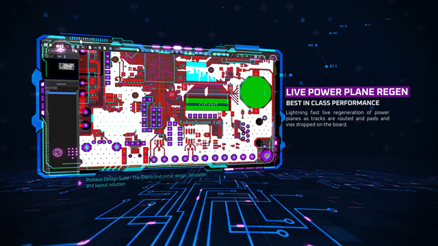
Power Planes in Proteus 9
A presentation highlighting the features and unique points of the Proteus 9 Power Plane systems.
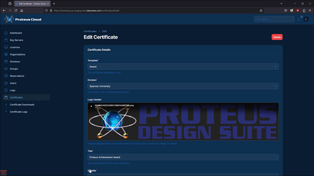
Proteus Cloud Certificates
The Proteus cloud license certificate system provides a way for achievement or completion certificates to be generated for users.
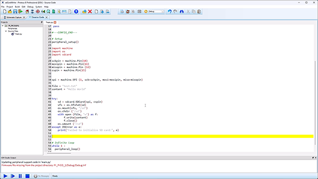
VSM for MicroPython
A quick project to show the end to end process for working with Micro Python and Proteus Design Suite. From creating a project to uploading the final code to the target device, this video will walk you through them all.
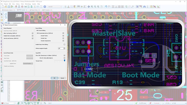
Route Command Centre
The Route Command Centre is now the hub to control the routing of a PCB on Proteus. Here you can select the tracking mode, editing restriction, visual display and track properties all from the press of a button.
Push and Shove
Proteus Design Suite now includes Push & Shove routing. The ability to move tracks and vias out of the way is coupled with the ability to switch to Follow Me Routing at the press of a button.
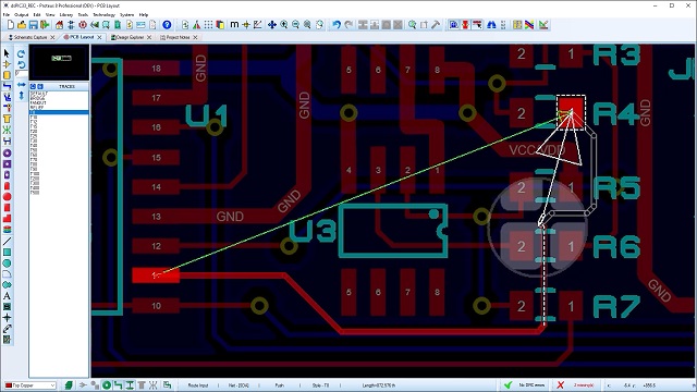
Design Rule Aware Editing
The Proteus PCB Design tool has been updated to include design rule aware track editing. This means any edits will adhere to the rules specified in the design rule manger.
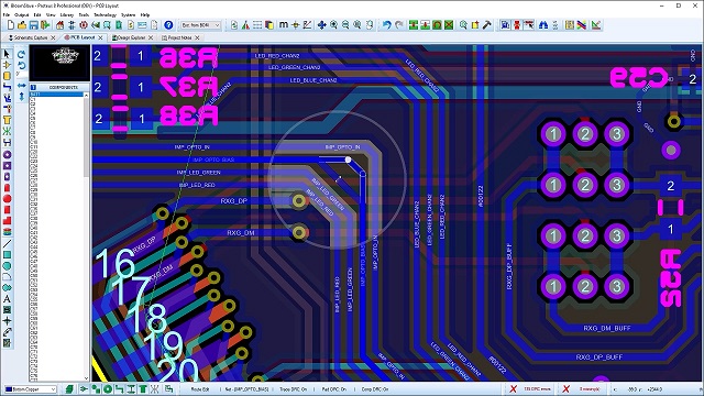
Visual Design Rule Checking
Track routing in Proteus PCB now displays a circular overlay which shows the design rule clearances around objects already placed on the board. This provides a clear view of where best to route.
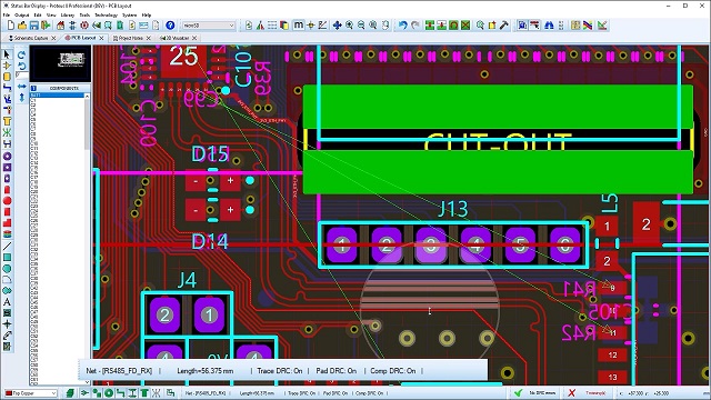
Status Bar Updates
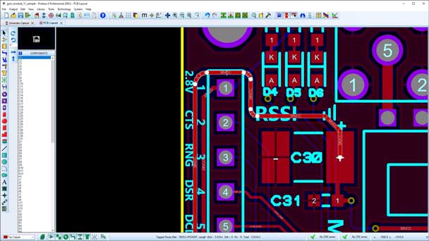
The status bar at the bottom of the PCB layout has been updated to include more information relating the the current tracking operation. This includes information on net and routing mode among others.
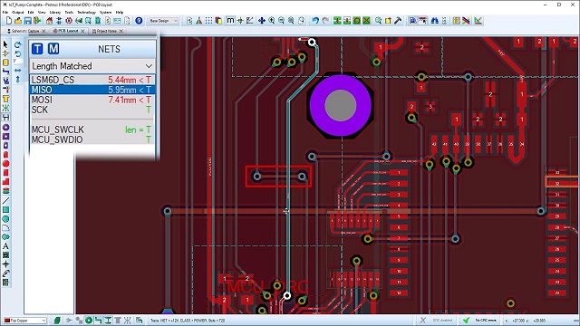
Length Matching Updates
The length matching function of the PCB layout tool has now been updated to ensure re tuning of match groups takes place automatically after an edit any one of the tracks in the group.
Curved Routing Update
The curved routing capabilities of Proteus PCB Design have been greatly improved. The new, smarter system will actively adjust corner radius as per user specified limits as well as curved mitres.
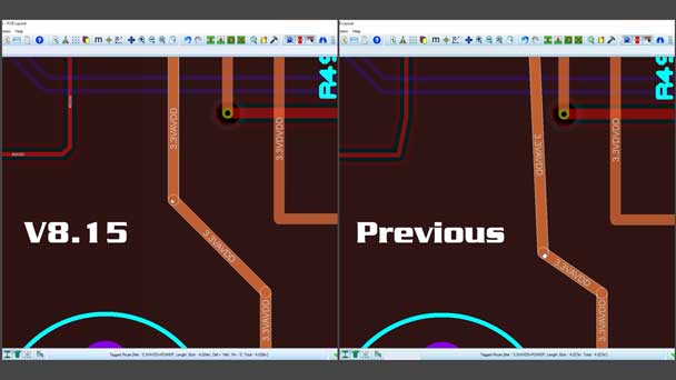
Linear Route Editing Proteus vprevious Update
Here we demonstrate the updates to the linear routing system in Proteus PCB Design. These include improved 45 degree route dragging and intelligent segment mitring.
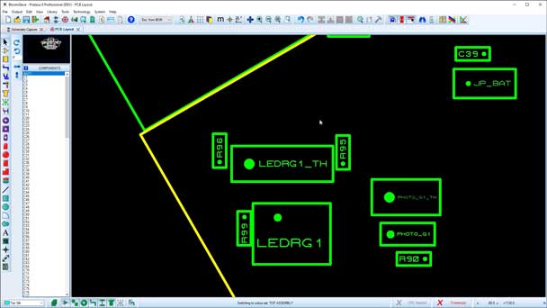
PCB Assembly Layers
In this video we demonstrate how the assembly layer of the PCB output can be applied and set with custom graphics ready for outputting to project specific documentation or PCB manufacture.
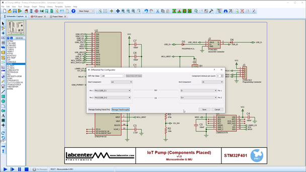
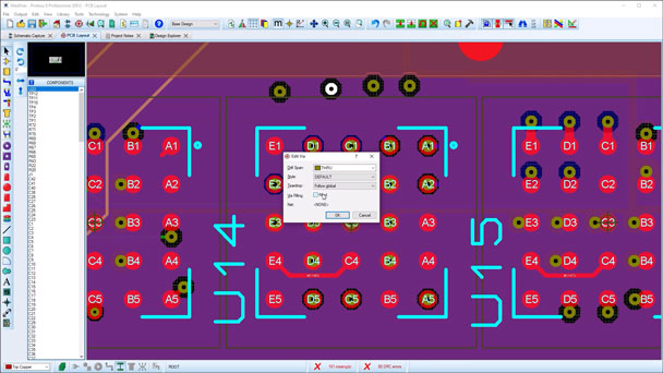
Diff Pair Configuration
This video provides a walk through on using the Differential Pair configuration tool. Specify start and end pins as well as pass through devices from a single, easy to use form.
Filled Vias
A short video to demonstrate the use of filled vias in Proteus PCB Design. These are type 7 vias in accordance with IPC-4761 specifications and can apply to single or multiple vias on a board.
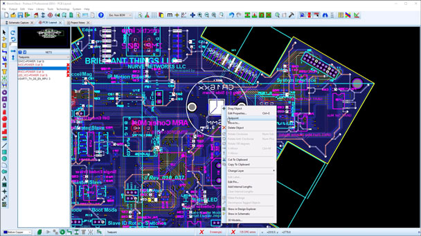
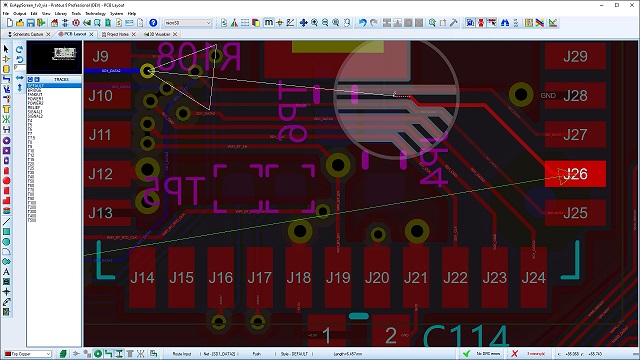
Test Points
A short video demonstrating the use of test points within the Proteus PCB design layout. Fully design aware with net specific rule settings allows for full compliance testing setup.
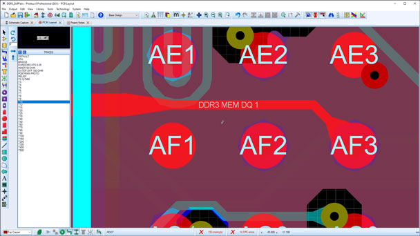
Teardrops and Tapers
This video demonstrates the updates to the dynamic teardrop feature of Proteus PCB Design. This now includes track tapering, ideal for route escapes from tight areas such as BGA Fanouts.
Miscellaneous previous
This video highlights some of the smaller, functional features added to the version previous release of the Proteus Design software. These are both user requested and development led features.
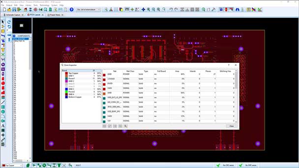
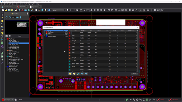
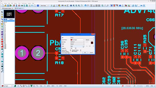
Zone Inspector
The Zone Inspector of Proteus PCB Design allows for an at a glance view of all copper pour zones on a board with details of their respective nets, layers and even area of coverage.
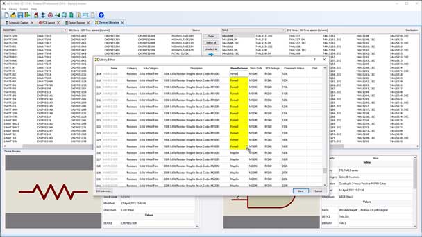
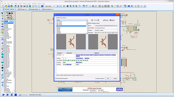
Library Part Editing
The ability to update and manage the properties of the Proteus component libraries. Update common properties or create your own to add libraries specific to your requirements.
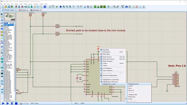
Design Walk
The Design Walk feature of Proteus allows the user to work through a design to confirm net connections across all sheets for added confidence in their design.
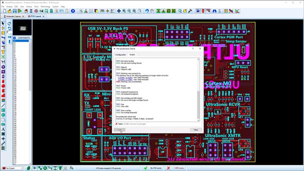
Pre Production Checker
PCB Pre Production Checker updates. This now allows for custom checks with greater ability to navigate to any errors and report retention for quick reference.

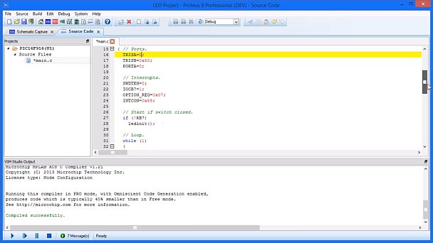
VSM Studio IDE
This video gives an overview of the VSM Studio IDE included with the Proteus Microcontroller Simulator showing both layout and basic functionality.
Differential Pair Pass Through
It is now possible to specify and use pass through components on differential pairs in the Proteus software. This is ideal for passive devices such as resistors on a phase matched pair.
Non-Functional Pads
Non functional pads are now supported in the PCB layout of Proteus Design Suite. This provides the ability to clear the annular rings around vias on layers where they are not connected to any traces.
Multi Board Designs
Proteus now includes full support for Multi Board designs. This allows for connected and associated boards to be designed in a single location with all files safely stored in a single project.
AutoSave and Backup
The autosave and backup system of Proteus ECAD Software has been updated to include custom backup paths, incremental project saving and system verified timed automatic autosaves.
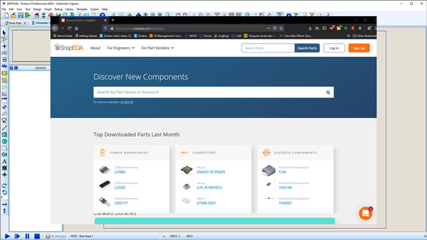
SnapEDA Web Search
As of Proteus CAD Software vprevious the component libraries automatically do a component web search of SnapEDA if the required device is not in local libraries and will add the part at the press of a button.
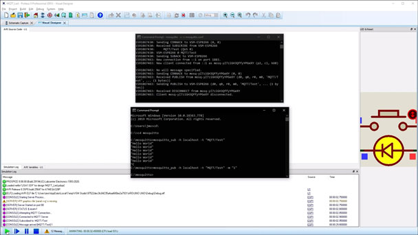
IoT Builder with MQTT
A demonstration the how IoT Builder can make use of the MQTT protocol to publish and subscribe to notifications and use the resulting state to trigger a system response.
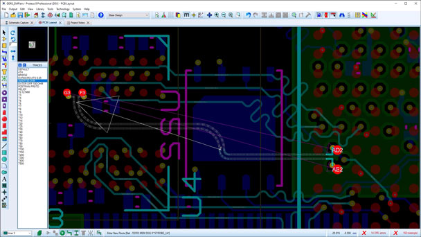
Differential Pair Routing
The Proteus Design Software has the capability to do differential pair routing with auto phase correction upon track completion and route length matching.
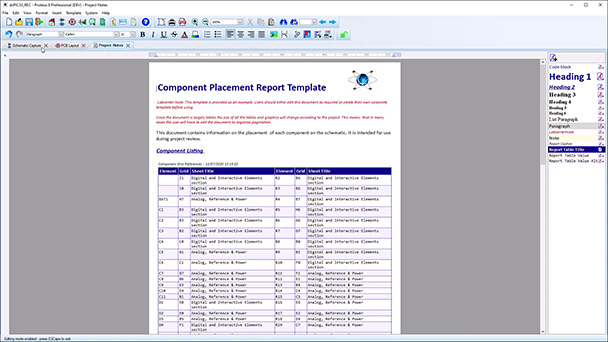
Component Placement Reporting
A short video demonstrating the the Component Placement Report available within Proteus. This gives sheet and grid positional information to quickly locate any device for review.
DXF to Copper Import
This video shows the process of bringing in a DXF file to the Proteus ECAD PCB layout. This allows for the graphic to be used either a copper filled zone or complex route such as NFC Coil antenna.
Design Reporting
This short video gives the overview of design reporting in the Proteus PCB CAD software and how it can be used with quality control and manufacturing instructions.
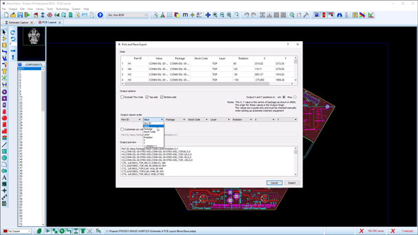
Pick And Place Files
A short video demonstrating the ability to customise the the details of the pick and place file in terms of both the information order and unique name of each of the file properties.
Miscellaneous Updates Vprevious
A short video demonstrating the small but requested updates included in the Vprevious release. These include highlighting pending changes and improved zone cross hatching support.
IoT Builder Arduino Authorisation Controls
A short video showing how IoT Builder for Arduino uses login controls for user authorisation and control access.
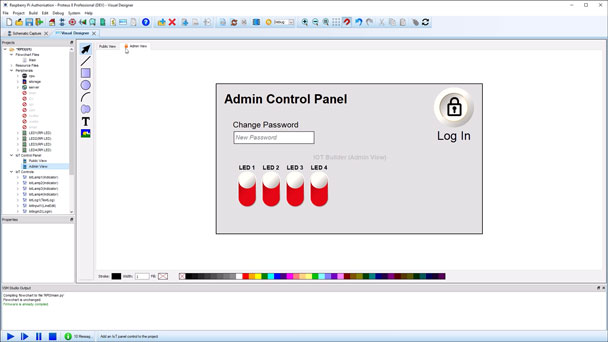
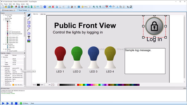
IoT Builder Raspberry Pi Authorisation Controls
A short video showing how IoT Builder for Raspberry Pi uses login controls for user authorisation and control access.
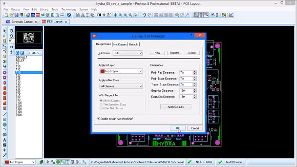
PCB Design Rules Manager
This video gives an overview of the revamped PCB Design Rule system in Proteus PCB Layout Software. This now introduces design rules by area room and greater clarity of rule violations.
Proteus Design Variants
This video shows the updated assembly variant feature in Proteus PCB CAD Software. This includes switching components with different values on different variants.
Power Planes (Copper Pour)
This video updates the use of the PCB copper pour in the Proteus PCB Layout Software. This includes the use of PCB Design Rules and board constraints.
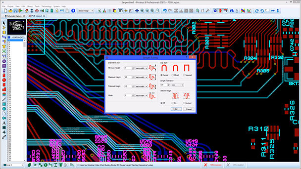
Length Matching
How to use the Serpentine Length Matching feature in Proteus PCB Design Software to create and edit groups of length matched traces on the PCB.
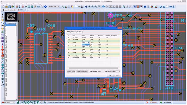
Layer Stackup
This video shows how Proteus PCB Layout Software makes use of a PCB layer stack. This allows dedicated Plane Layers as well as Smart Vias and intelligent drill ranges.
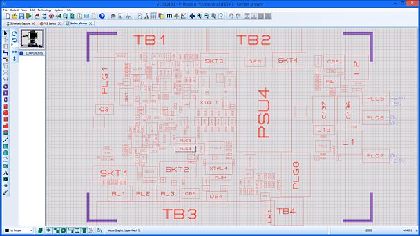
Gerber X2 File Format Output
This short video shows the new Gerber X2 file format that is now included in Proteus PCB Layout Software, including how to generate Assembly diagrams from the output files.
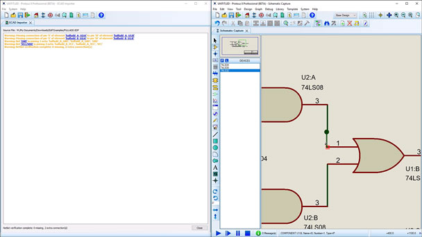
EDIF2 File Format Import
The Proteus ECAD Software has the capability to import EDIF2 file format schematic designs as exported from the OrCAD v9.2 and v17 software.
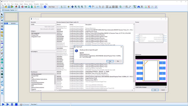
Component Library Web Search
The Proteus CAD Software component libraries automatically do a web search if the required device is not in local libraries and will add the part at the press of a button.
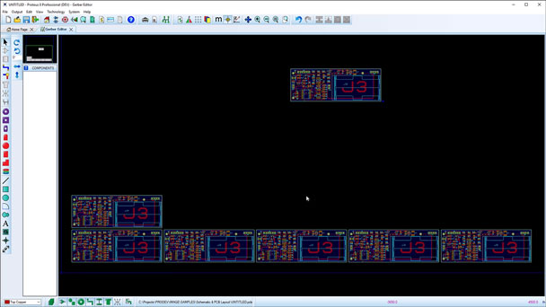
PCB Panellization
Proteus EDA Software has greater support for producing manufacturer ready panelled boards from Gerber X2 files including automatic board placement and spacing.
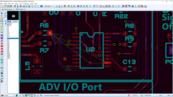
Auto Track Completion
The Proteus EDA Software provides a quick method to route your PCB Designs by using click to complete technology to place tacks along valid paths.
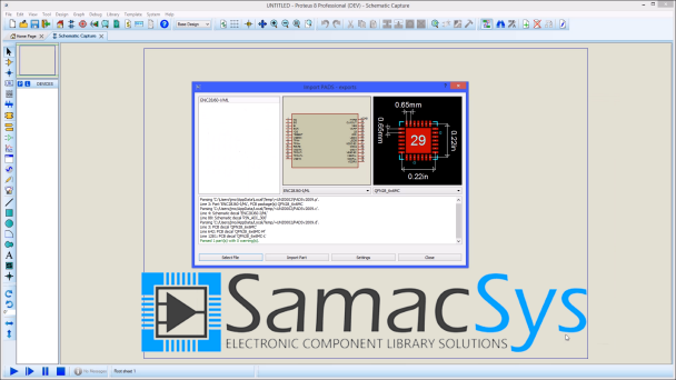
Part Import from Samacsys
This video shows how to import schematic components, PCB footprints and 3D STEP models from Samacsys Library Loader directly in to Proteus EDA Software for use in your designs.
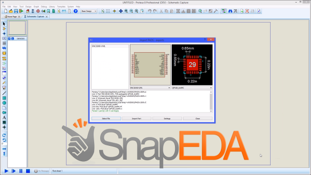
Part Import from SnapEDA
This video shows how to import both schematic components and PCB footprints from SnapEDA directly in to Proteus PCB CAD Software for use in your designs.
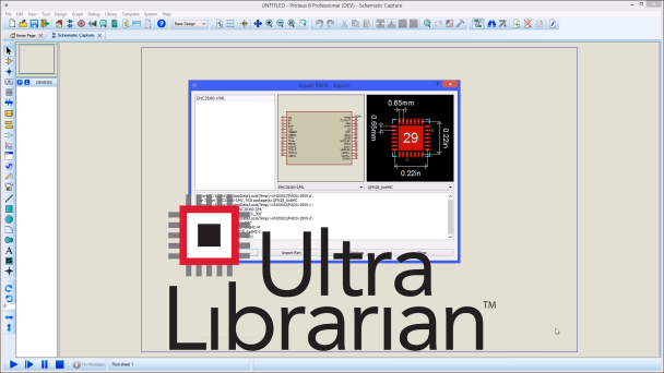
Part Import from Ultra Librarian
How to import schematic components, PCB footprints and 3D STEP models from sources such as Ultra Librarian and Digi-Key directly in to Proteus PCB CAD Software.
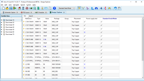
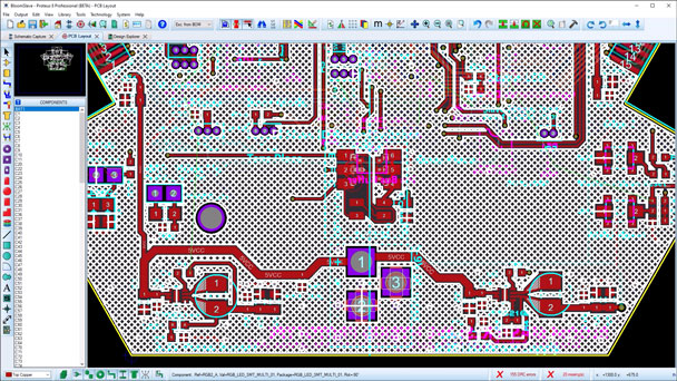
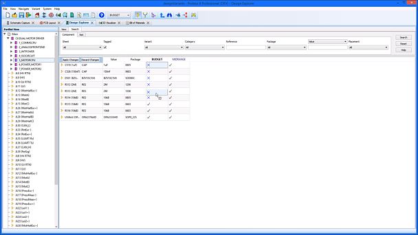
Design Explorer
A short video demonstrating the design explorer module in the Schematic Capture Software. This allows cross probing of the schematic and PCB and control of Assembly Variants.
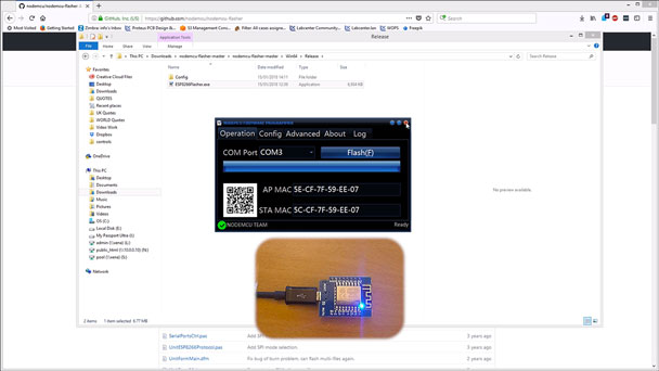
Using an 8266 with IoT Builder
This video shows how to create a your own Internet of Things shield for Arduino Uno or Mega and use it with IoT Builder from Proteus to design and create your own front panel apps.
BSDL File Import
This video shows the updated process for importing BSDL files in to the user schematic parts library of Proteus Schematic Capture software for version previous and later.

Raspberry Pi Setup
This video explains how to set up the Raspberry Pi for first use and Simulation with Proteus Visual Designer and IoT Builder. This allows for simple programming of IoT project designs.
IoT Builder Introduction
An introduction to using IoT Builder with Visual Designer to create a project for an Internet of Things connected Arduino and control it from a tablet or mobile device.
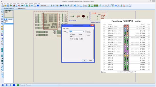
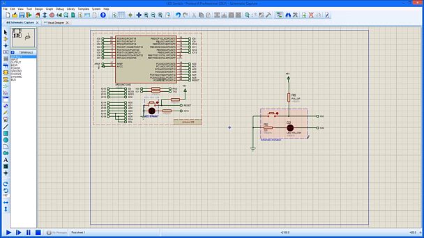
Raspberry Pi LED Switch Control
A short video demonstrating how to use Proteus MCU Simulation software to run a Raspberry Pi Simulation and control the GPIO pins in firmware and hardware.
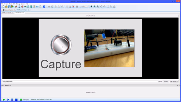
Raspberry Pi and IoT Builder
This video demonstrates the Raspberry Pi using IoT Builder by Proteus to control the Raspberry Pi Camera and display the images taken in Simulation and hardware..
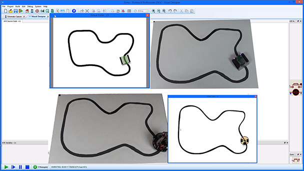
Visual Designer Arduino Turtles
This video gives an overview of the use of Visual Designer with different Turtle robots available for Arduino.
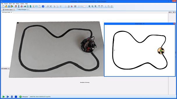
Visual Designer Arduino Zumo Turtle
This video displays the ability of Proteus Visual Designer and Arduino Simulation to control and program the popular Zumo Arduino turtle robot.
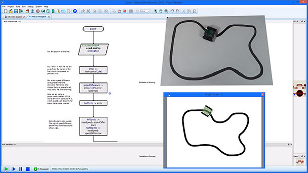
Visual Designer Arduino Funduino Turtle
How to control a Funduino Arduino Turtle inside Proteus Visual Designer using Embedded simulation and flowchart debugging
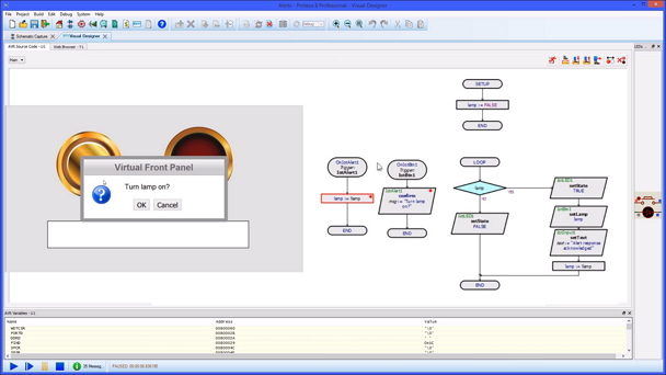
IoT Builder Timer controls and functions
How IoT Builder uses Timers to interact with the internet of things. These allow for activities such as repeat routines, countdowns and alarms.
IoT Builder Alerts
How to use alerts with IoT Builder by Proteus. Alerts are powerful tools that can inform users of situations or require a user response for the Internet of Things program running.
Library Manager
An overview of the updated Library Manager with component comparisons for Proteus EDA Software allowing greater control of user created components and footprints.
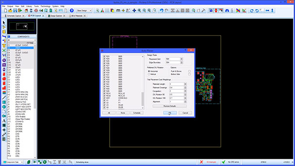
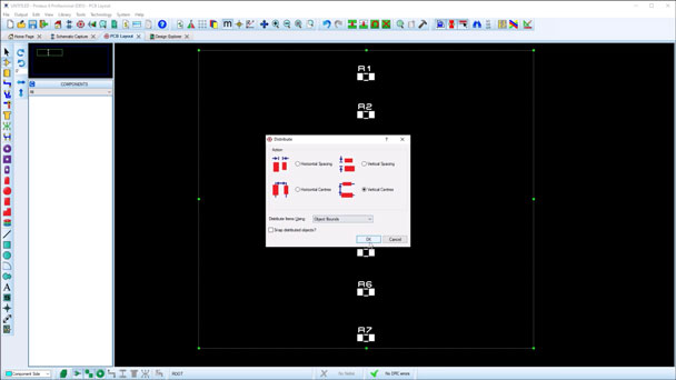
Auto placement Floor Planning
A look at the Placement Room feature of the PCB Layout Software. This allows you to group critical components together when you set board constraints.
Zone Via Stitching
Via stitching and shielding features now included in Proteus PCB layout software. An automated process working alongside your PCB Design Rules and board constraints.
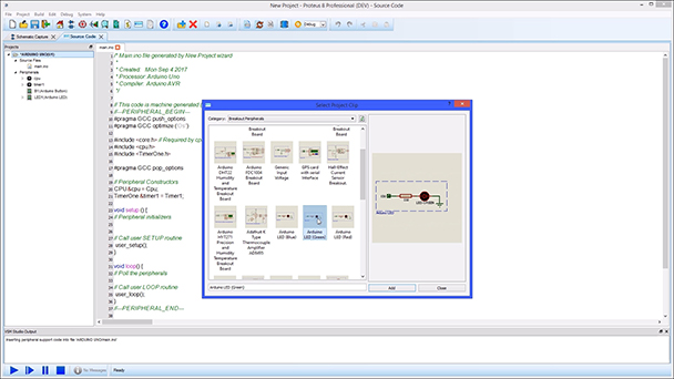
Arduino VSM
This video shows how to use the drag and drop feature for the Arduino Simulator using peripherals, shields and break out boards in Proteus Microcontroller Simulation software.
IoT Builder Extended Use
Using IoT Builder by Proteus to control and debug an Arduino design from a connected device during an Internet of Things simulation.
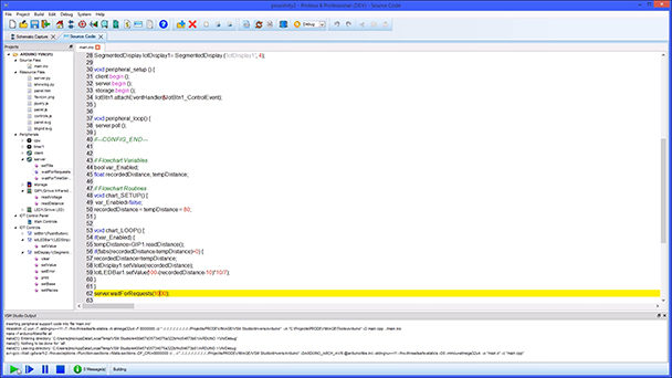
IoT Builder Code Writing
How to create an Internet of Things project directly for Arduino using code and IoT builder controls. All done with interactive Arduino simulation, debugging and one click deployment.
TFT Display Shield
This video demonstrates Visual Designer for Arduino AVR simulation using a TFT Display Control with schematic capture software interaction and hardware deployment.
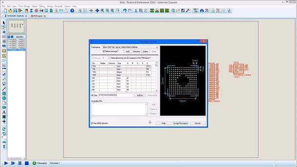
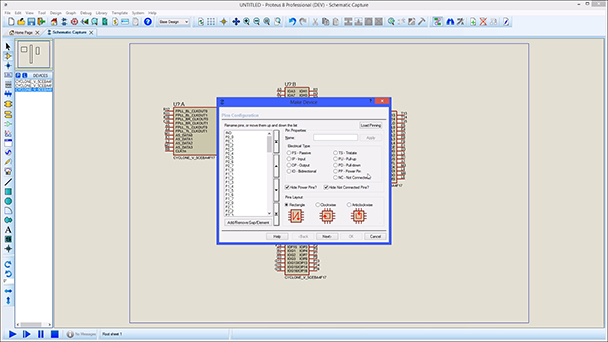
Large Pin Count Devices
This video shows how Proteus EDA Software can handle large pin count devices such as FPGAs and BGAs by splitting them into multiple schematic parts and easy pin remapping.
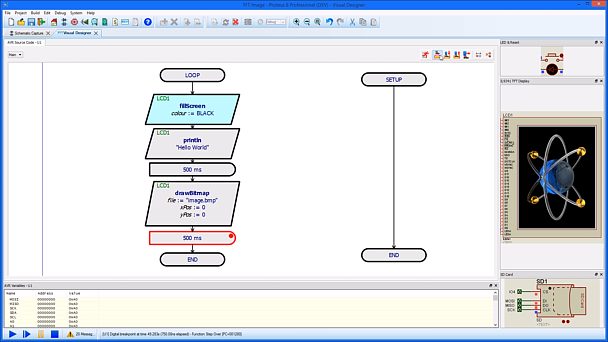
Visual Designer Debugging
This video shows the different ways your are able to debug a flowchart project inside Proteus Visual Designer for embedded Arduino and Raspberry Pi simulators
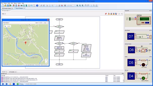
Visual Designer GPS Alarm
This video shows Visual Designer using the Arduino GPS breakout board using the Proteus Arduino Simulation tools for embedded systems.
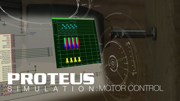
PWM Control on the Schematic
Visual Designer using Proteus Schematic Capture Software as a virtual Breadboard to run a motor with a PWM signal and see the results with the Arduino Simulator.
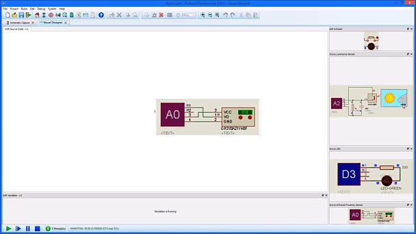
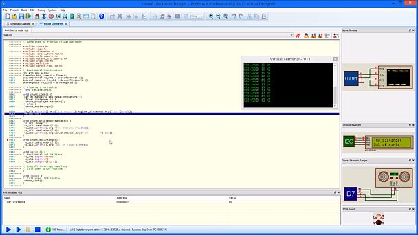
Grove Night Sensor
Proteus EDA Software using Visual Designer for Arduino AVR and Grove sensors to create a simple Night Light with full microcontroller simulation.
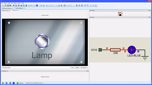
Visual Designer Flashing An LED
Visual Designer can use Proteus Schematic capture software as a virtual breadboard to create interactive circuits during the simulation for either Arduino or Raspberry Pi.
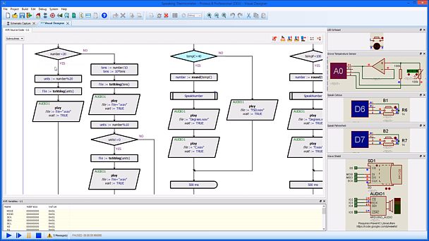
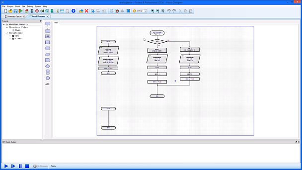
Speaking Thermometer
A short video using Visual Designer to single step and debug a talking thermometer project design with Arduino Simulation and Schematic Capture Software interaction.
Circuit Re-Use
This video shows how to reuse sections of common circuitry across various designs and easily recreate sub circuits and PCB layouts in the Proteus EDA Software
Track Editing
This video show how to edit and adjust one or several tracks at once for a quicker, smoother work flow in the Proteus EDA Software during the PCB layout process
Miscellaneous V8.2
A summary of some of the smaller new features in the Version 8.2 release.
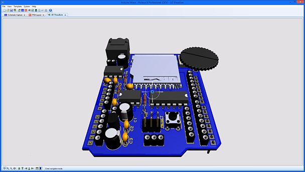
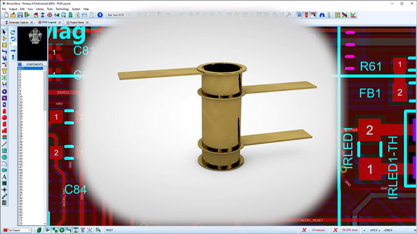
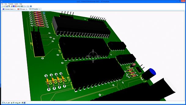
3D Visualisation
This video shows the use of the 3D viewer module in Proteus PCB CAD software including the import of component STEP files and export of full board STEP and IGES format models.
Active Popups
This shows how to use the Active Pop-up feature in Proteus schematic capture software to get a smoother working environment during the debugging stage of MCU simulation.
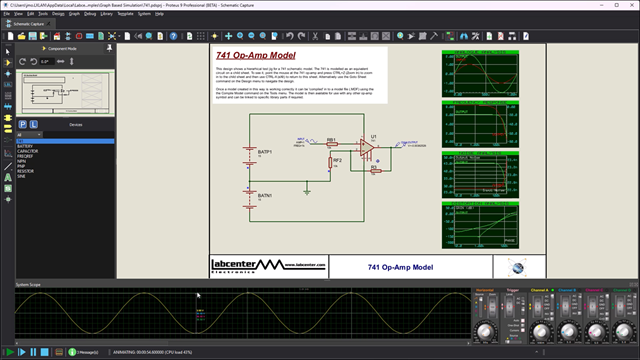
Advanced Simulation Features
This videos shows the use and functions of the Advanced Simulation Features in Proteus CAD Software for graph based analysis of schematic capture designs.
Auto-Routing
This video shows the constraint driven auto router function inside the PCB Design software for a powerful PCB Layout tool.
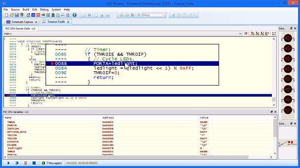
Software Breakpoints
This video shows how to set breakpoints in the firmware of a microcontroller in Proteus Embedded simulation software for debugging purposes.
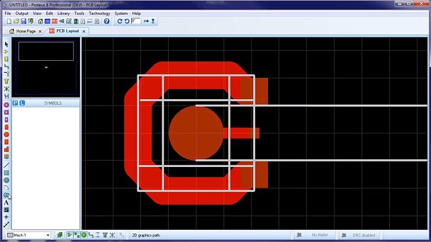
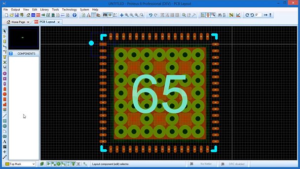
Creating Button Pads
This video shows how to create complex footprints, such as Button Pads, inside the PCB layout module of Proteus PCB CAD Software.
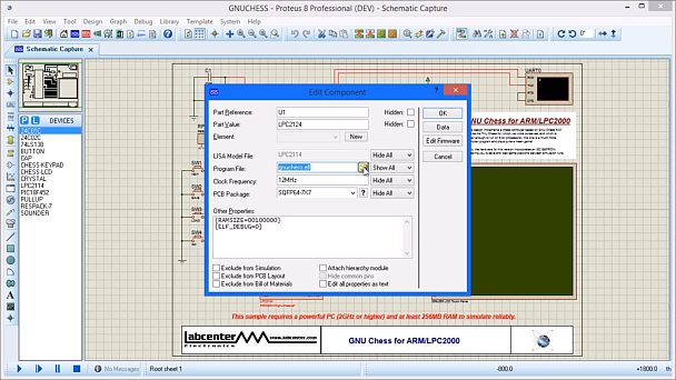
Debug Files
This video shows how to set the Debug Files for Microcontroller simulation inside Proteus schematic capture software for simulation purposes.
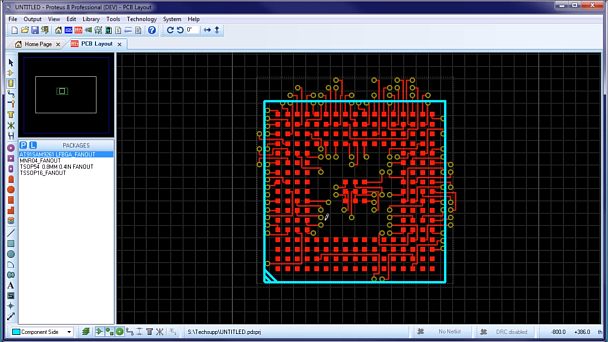
Storing Fanouts in Packages
This video shows how to save a component footprint in the PCB CAD Software with a pre-defined track Fan-out for use with future Proteus projects.
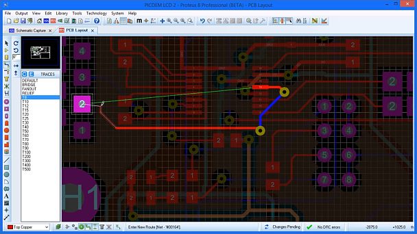
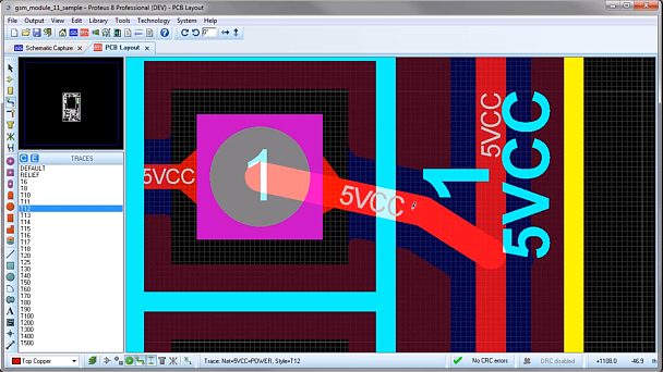
Manual Routing
This video shows how the Follow-Me Routing feature of the PCB Layout Software module in Proteus Design Suite works during track placement.
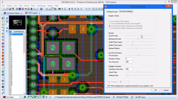
Hardware Accelerated Display
This shows how Proteus EDA Software can make maximum use of your computers graphics card to get high quality detailed displays of your PCB during the design process.
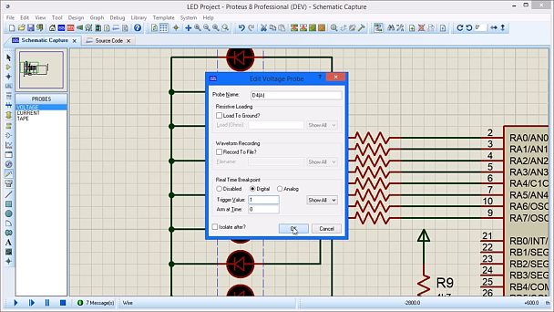
Hardware Breakpoints
This short movie shows how to use voltage probe conditions to trigger breakpoints during a microcontroller simulation in the Proteus schematic capture software.
STEP/IGES File Format Support
Proteus PCB Design Software can import 3D models in the STEP and IGES formats for use within the 3D viewer and export boards for use in your preferred MCAD software package.
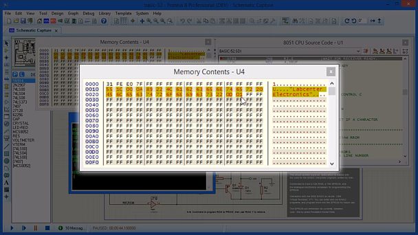
Persistent Memory
This video shows how the Proteus Microcontroller Simulator utilizes Persistent Memory during simulation for components such as EPROM.
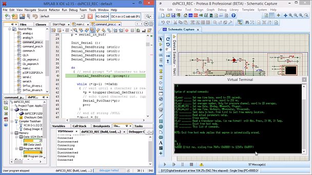
MPLABX Driving Proteus VSM
How to slave the Proteus Microchip Simulation software to the MPLABX IDE so that the simulated hardware in the schematic capture can be debugged inside MPLABX.
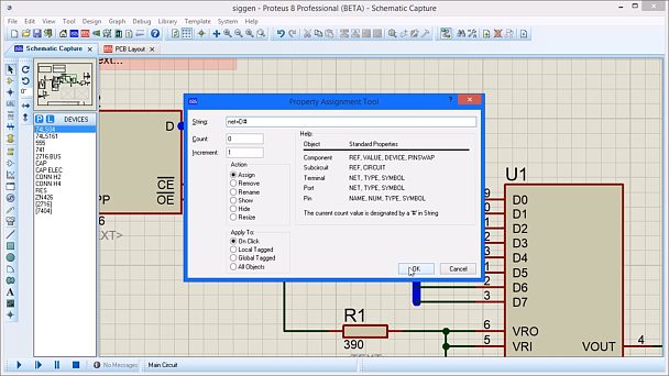
Property Assignment Tool
This video shows how to use the Schematic capture software Property Assignment Tool to quickly and easily edit and update a schematic layout in Proteus Design Suite.
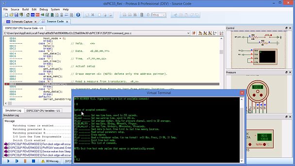
Proteus Using XC16 Compiler
This video shows how Proteus Microchip simulation can automatically configure and compile firmware using the Microchip XC16 Compiler.
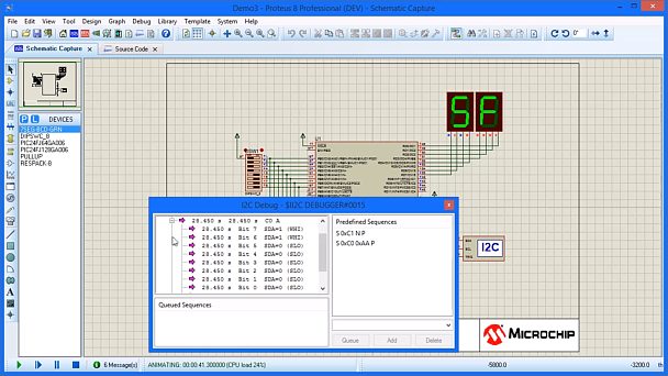
Protocol Analysers
How to use the Protocol Analyser in Proteus schematic capture software to look at and control devices on the I2C bus of a simple design whilst using embedded simulation.
Advanced Footprint Creation
This video shows how to manually create advanced footprints with specific requirements such as stitched pads or stippled paste masks in the Proteus PCB CAD Software.
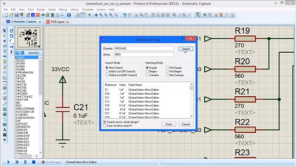
Search And Tag
This video shows how to use the Search and Tag function for Proteus schematic capture software.
Selection Filter
This video demonstrates how to use the PCB Layout Selection Filter in Proteus PCB Design Software to select all or limited items on a PCB design.
Dynamic Teardrops
This video shows how to use and adjust the automatic Teardrop track connections in the PCB Layout software of the Proteus Design Suite for more reliable trace connections.
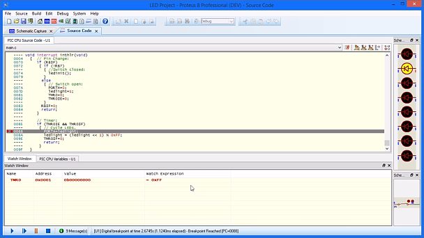
Watch Window
This video demonstrates the use of the Watch Window during firmware debugging whilst using VSM Studio for Proteus Embedded Simulation software.